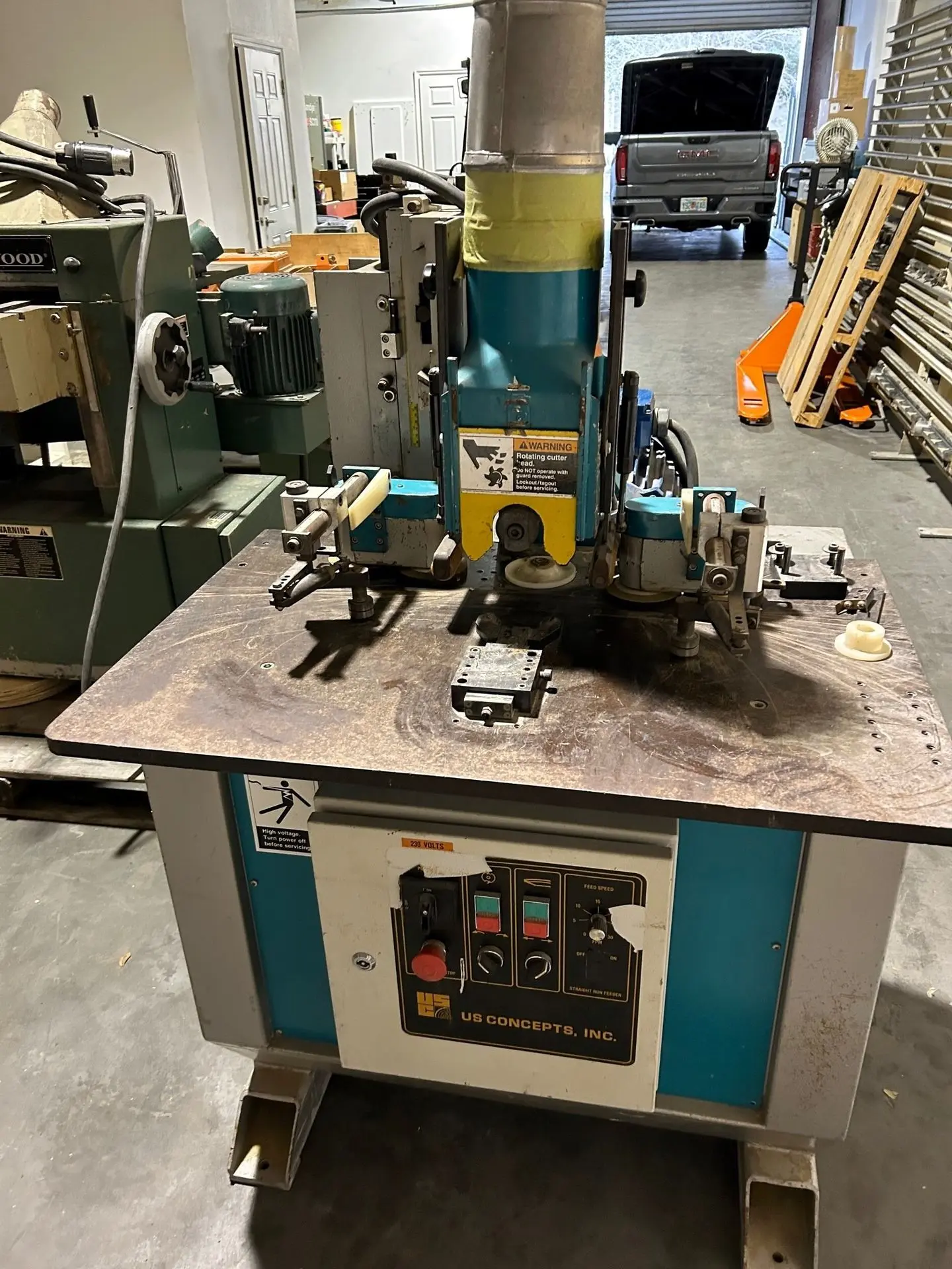
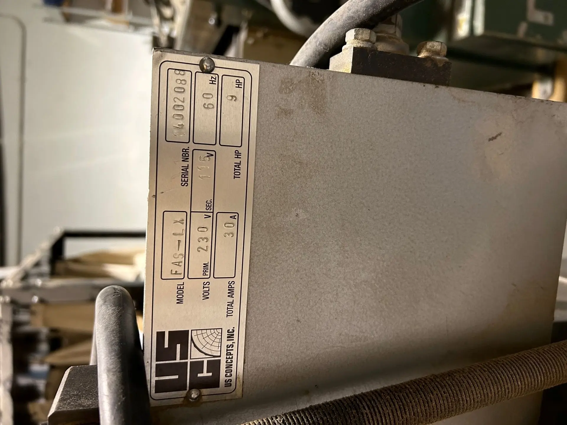
FAS-LX
UNIVERSAL ARCH MOULDER
$6,000.00
Operation Manual
SAFETY INSTRUCTIONS
This machine can cause serious injuries if all safety precautions are not taken or if the machine is used improperly or used by unqualified, untrained or careless personnel. ONLY fully trained and alert personnel should attempt to maintain, service or operate this machine. Be constantly alert to possible safety hazards on or around this machine.
Become completely familiar with the operating instructions and all safety instructions supplied with the machine before attempting to do anything with or to the machine. Cut the machine off at the first sign of any problem.
1. Do not attempt to operate or work this machine unless thoroughly trained in its safe operation and maintenance.
2. Guards and holds have been installed for your protection; do not operate this machine without having them in place and properly adjusted.
3. Do not wear loose clothing which could get pulled into the machine. Remove wrist watches jewelry and gloves. Long hair should be protected under a head cover.
4. Wear proper eye protection or face shield when the machine is operated. Do not expose your eyes or face to the danger of flying sawdust, debris or wood particles. Never stand directly behind a board being fed into the machine. “MATERIAL KICKBACK” can occur.
5. Keep your hands well away from the feedworks area and all moving parts, particularly the cutting and rollers.
6. Before attempting to clear any jams or attempting to make any repairs or adjustments to the machine, turn off the power and make sure all moving parts have come to complete stop and make sure the machine cannot be accidentally re-started.
7. De-energize the machine electrical panel and secure against accidental re-start by using lockout on the control cabinet before changing cutterheads, blades or knives. Be sure that cutterheads or blades are at a full stop before attempting any work on them and before investigating any problems.
8. Wear proper ear protection when the machine is in operation.
9. Do not operate while under the influence of Drugs, Alcohol or Meditation.
INTRODUCTION
We ask you to observe the following instructions:
• This manual should be accessible at all times to the workers responsible for this machine.
• This manual as well as this machine are subject to constant improvement to keep up with technological advancements. In these circumstances, this manual may differ in some solutions from the supplied machine. In case this happens please contact us for help. We are always ready to give you assistance and advice.
To obtain the required results by means of this machine, all the instructions comprised in this manual should be observed. When contacting us, please refer to the serial number and purchase date of the machine.
We wish you success with your new FAS-LX Universal Arch Moulder.
GENERAL DESCRIPTION
FAS-LX Universal Arch Moulder consistently cuts curved profiles by using a unique floating feed system that registers on the outside edge of the curved blank. The FAS-LX is equipped with two-axis spindle adjustment in order to easily and accurately match the cutter to the moulding profile.
STANDARD FEATURES
• Spindle diameter 1 ¼”
• Max. cutting width 6”
• Max. cutting diameter 6 ½”
• Max. material height 4 ½”
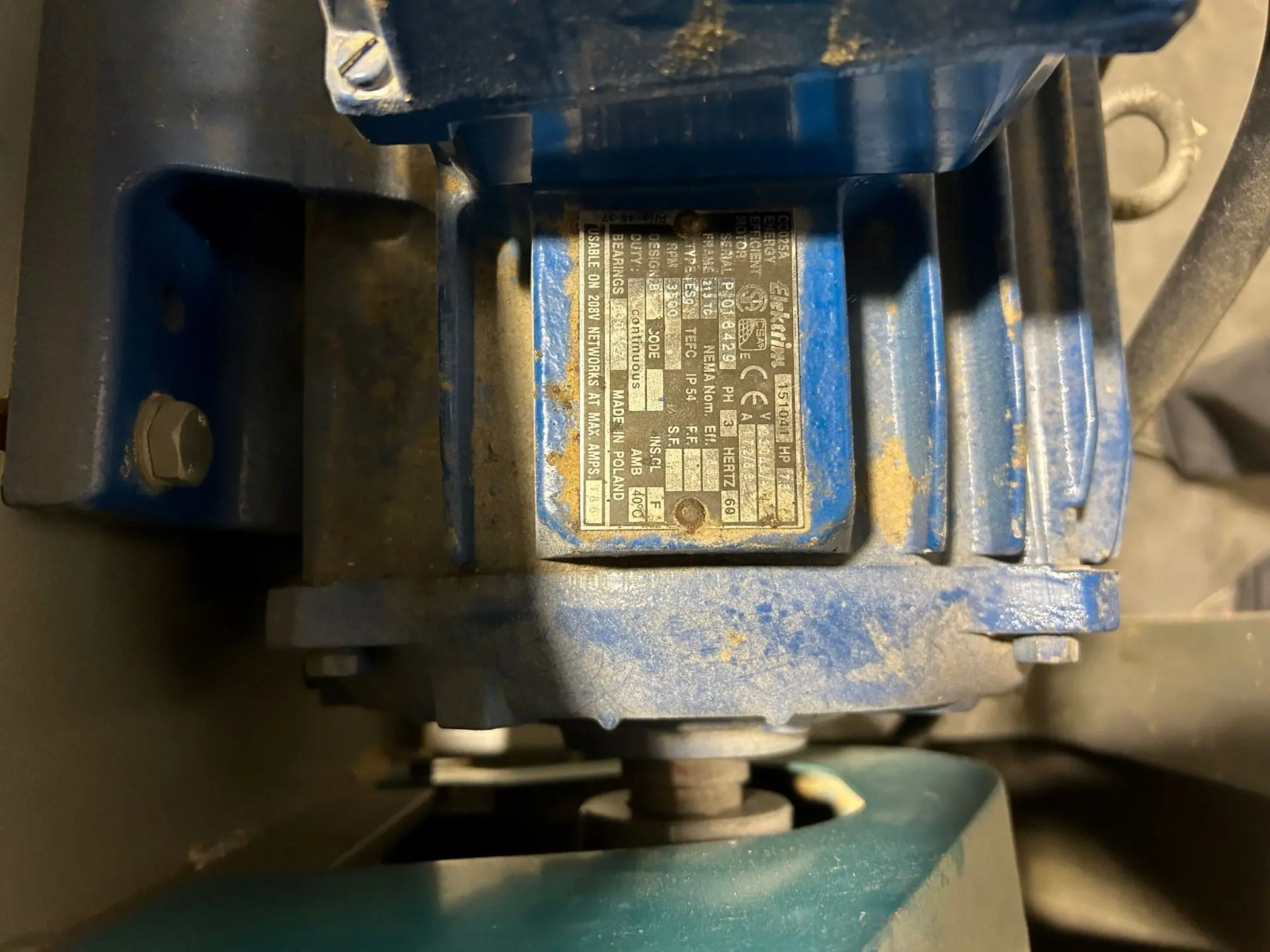
• Main Motor 7 ½ HP
• Feed Speed – adjustable 0 - 30 FPM
• Table size 36” x 24”
• Spindle tilt 0 - 52°
• Machine weight (fully equipped) 1475 lbs.
OPTIONAL FEATURES
• 460V, 380V, 575V – 3 phase electric
• Forward – Reverse controls
• Straight run feeder
• Flip-up table extensions
• Locking fixture for true radiuses
Connection to the electrical network
The electrical connection should be performed by qualified electrician according to all electrical codes.
The electrical apparatus is located in the control box. The machine requires 208-230V or 460V three-phase power. The power supply cable should be connected to the outside terminals of the main disconnector.
Before proceeding to connect the machine to the factory electrical network, the following should be checked:
a. If the electrical equipment of the machine conforms to the electrical network which is being used in the factory: voltage, frequency, etc.;
b. Pay attention to the electrical apparatus if it has not being damaged during transportation. All damaged wires and elements should be replaced, maintaining the same rated values.
c. Pay attention to all the screws and nuts of the electrical apparatus and to the means by which the electrical leads are connected. The screws, which have become loosen during transportation, should be tightened.
d. Carry out all proper neutralization or the protective grounding depending of the local codes.
e. Proper size disconnector with circuit breaker should be installed.
f. During the test starting, the protection state of the machine in respect to the industrial safety and the correctness of rotation should be checked. Be sure that there is no tool in the spindle.
g. Basic condition of the correct operation of the electrical apparatus and the motor is the suitable voltage rating in the network, which varies no more than +/- 10% of the set voltage.
INSTALLATION
The FAS-LX Universal Arch Moulder requires no special foundation and can be set directly on the floor of the proper load capacity. The machine should be leveled and fastened to the floor.
CONTROL PANEL

1. - Main Disconnect ( always turn it OFF while setting, servicing or not working)
2. - Spindle START-STOP push-buttons
3. - Feed START-STOP push-buttons
4. - Speed potentiometer for feed speed adjustment
5. - EMERGENCY STOP push-button
6. -Optional - spindle Forward-Reverse switch. Normal rotation of the spindle is counterclockwise. For reverse rotation (clockwise) turn the switch to right and hold while pressing Start switch.
7. - Optional - feed Forward-Reverse switch
8. - ON-OFF switch for optional straight run feeder
PREPARATION FOR INITIAL START UP
The machine should be cleaned from dust, and the protective grease should be removed from all surfaces. Cover the cleaned surfaces with spindle oil. Wipe the table and the other elements clean. Lubricate to the lubrication instruction.
This machine has been examined by the producer. However, during transportation some parts may have become loosened. In these circumstances, staring this Arch Moulder can cause damage, therefore, before test starting check for any loosen screws, nuts, etc.
TOOLS
FAS-LX Universal Arch Moulder will accept either the solid cutter with min. diameter 4-1/8” (bottom of the profile) and max. diameter 6 ½” (tip to tip) and 1 ¼” bore certified for min. 6500 rpm, or the moulder head for corrugated back knives. Maximum head length is 6”, and maximum diameter 5”. However, in order to utilize full depth of cut and minimize the profile distortion in sharp radiuses we recommend using the 4” diameter head. Make sure that maximum cutting circle (tip to tip) is 6 ½”. Only the perfectly matched, balanced, and firmly mounted knives can be used on this machine.
WARNING ! Using tools other than described above may cause and accident and serious injury or death.
CHANGING THE TOOLS
Using the special wrench supplied with the machine hold the spindle end cap and unscrew the centrally located socked head cap screw with the 8 mm Allen wrench. When installing the cutter that is narrower than 6”, the proper size spacer has to be used. Make sure the end face of the spacer or of the head extends enough in order to ensure proper squeeze by the end cap.
MATERIAL BLANKS
Since material slides on the table and the cutter cuts from the top, the clean bottom surface is important to achieve uniformed thickness and clean cut. The feeder guides the material of the outside edge, therefore this edge has to be finished with high accuracy. Any dent or hump on the edge will reflect on the cutting face.
In order to make feeding easier, and avoid any profile distortion on the beginning or the end, we suggest to prepare blanks approx. 4” – 6” longer on each side for trimming after profiling is done.
SETTING THE WIDTH OF THE MOULDING
The two side pressure rolls # 4 are set to the width of the workpiece. Loose the screws # 5, and slide the two pressure rollers to the correct clearance to press the workpiece firmly against the drive rollers # 3 at the rear. The center pressure fork # 6 is then set in a similar manner after loosing the screw # 7. The center fork must apply sufficient pressure to keep the workpiece in the constant relation to the cutterhead as it passes through the machine. The fork spring tension can be corrected by screw # 8. A test workpiece should then be fed through the machine without shaping or sawing, so that any necessary correction can be made to the feed.
WARNING! In order to prevent a dangerous kick-back of the workpiece the proper hold-down setting must be checked every time the height of the cutter is reset or the thickness or width of the material has been changed. Never stay behind the piece you feed in especially when you cut the straight blank or very large radius.
CENTER GUIDE ROLL
The central guide roll # 2 on page 6, supplied with the machine may not be ideally suited to your workpiece. A choice of two interchangeable guide rolls is available. The central guide roll is made out of plastic material, so if necessary the knife can cut into the roll. The feed must be on while digging into the guide roll.
TOP PRESSURE (hold down) ROLLERS
Set the top pressure rollers on each side of the cutterhead so the workpiece is always slightly pressed against the table top.
You can do so by releasing knurled knob above the hood and sliding the gas spring holder down.
ATTENTION!
The to pressure roller setting must be changed accordingly with any changes of the cutter height or material thickness.
ADJUSTING THE FEED RATE
The rate of feed is infinitely variable by means of the black knob on the control panel of the machine. Direction of the feed can be changed by flipping the selector switch on the control panel. The motor has to be restarted after every change.
In order to achieve very smooth finish on the large profile, the work piece may be run twice through the machine by cutting approximately 80-90% of the material in the first run and cleaning the rest in the second pass.
SPINDLE ADJUSTMENT
The spindle with the cutterhead can be adjusted up and down with the screw # 10, and in-out with the screw # 11, for fine adjustment use screw # 11A. For better stability, you may tighten the gib screw on the dovetail slides after the position of the cutterhead is set. The spindle can be tilted down with the help of the screw # 12 after loosening all four nuts # 13. Make sure that the nuts #13 are tighten back after the spindle angle is set.
MAINTENANCE
In order to ensure a prolonged live time, the machine should be suitable maintained by observing the following instructions:
• Every day after completion of work, the machine should be cleaned carefully;
• The machine should be inspected periodically for loosened screws and nuts. Tighten all loosened screw immediately;
• Periodically inspect condition of the grounding conductor and the electrical lead connections and tighten screws to the terminals which may became loosened;
• Lubricate the top and bottom pillow block with the regular bearing grease every 3 months.
• Lubricate spindle bearings with quality bearing grease like Mobil Polyrex EM every 3 months.
- Once a year check the oil level in the feed gearbox under the table.
 US
CONCEPTS, INC.
US
CONCEPTS, INC.
31W021 NORTH AVE. WEST CHICAGO, IL 60185, ph. 630-876-3110, fax 630-876-3114
FAS-LX
UNIVERSAL ARCH MOULDER
Your business and relationship are very important to me as your representative at Spence Machinery and to our entire company.
If you wish to proceed with this order, please indicate so by signing in the space provided below and returning a copy of this offer as soon as possible. Prices can only be held for 30 days from the date of this offer unless otherwise stated used machines are subject to prior sale. Payment terms for machinery are 60% with order, 40% prior to shipment. Sales tax in Florida will be due unless a Special Exemption Form is completed with the order.
Thank you for the opportunity to assist you with the production machinery requirements for your company. We look forward to doing business with you. Please don’t hesitate to contact me if you have any questions.
Sincerely,
______________________________
Ordered By
Sam Spence ______________________________
407-509-8150 Title and Date
SUGGESTED EXEMPTION CERTIFICATE
FOR PURCHASES OF INDUSTRIAL MACHINERY AND EQUIPMENT, PARTS,
AND ACCESSORIES
[Note: This certificate may be a separate document attached to a purchase order, or may be incorporated within a purchase order itself.]
I certify that the industrial machinery and equipment, parts, or accessories purchased on or after 03/29/2023 (Date) from __Spence Machinery Company, LLC_______________ (Vendor's Name) are exempt from sales tax under paragraph 212.08(7)(kkk), F.S.
The machinery and equipment will be used by an eligible manufacturing business at a fixed location in Florida at __________________________________________ (Street Address and City), Florida, to
manufacture, process, compound, or produce items of tangible personal property for sale. The parts and accessories purchased for the machinery and equipment will be used at such location and are purchased
prior to the date the machinery and equipment are placed into service.
I certify that ______________________________________________ (Name of Purchasing Business) is a
business establishment contained within an industry classified under NAICS codes 31, 32, or 33, as contained
in the North American Industry Classification System, as published in 2007 by the Office of Management and
Budget, Executive Office of the President.
I understand that if I use the machinery, equipment, parts, or accessories for any nonexempt purpose, I must pay tax on the purchase price directly to the Florida Department of Revenue.
I understand that if I fraudulently issue this Certificate to evade payment of the sales tax, I will be liable for
payment of the sales tax, plus a penalty of 200% of the tax, and may be subject to conviction of a third degree
felony.
_________________________________________ _________________________________
Purchaser's Name (Print or Type) Title
_________________________________________
Purchaser's Signature
_________________________________________ __________________________________ Florida Sales Tax Number Federal Employer Identification
_________________________________________ __________________________________ Date Telephone Number
This certificate relieves the vendor from the responsibility of collecting tax on exempt sales amounts.
The Department will look solely to the purchaser for recovery of tax if the purchaser was not entitled to the exemption.
Form to be retained in vendor's records.